By Admin / 26 Aug 2026
How Kinematics, Liquid Dynamics, and Production Speeds Dictate the Right Motion Profile for Your Packaging Line
- Engineering
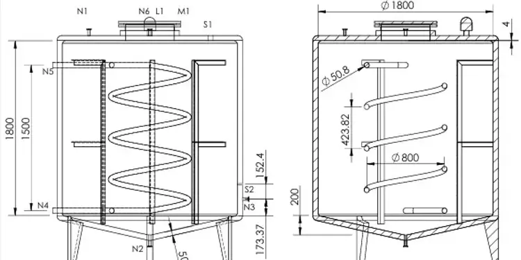
When a client came to us with a palm oil storage and melting facility, the brief looked simple on paper: keep three tanks fed with hot water on demand, melt solidified palm oil fast enough to meet a 2,000 kg/day target, and do it without any single process starving another. In practice, it turned into one of the more interesting control-system puzzles I've worked through at MEPL — and a good example of how a small hardware change can ripple through an entire thermal and control design.
I built the resulting control architecture and call it ADA — Adaptive Demand Allocation Architecture. Here's the story of its latest design revision, and the surprising thing it taught me about where "cost" actually hides in a system like this.
A quick note up front: this design is complete and has gone through rigorous engineering calculation, but the system has not yet been physically installed or commissioned. Everything below reflects analysis and modelling, not field measurement — we'll follow up once it's running.
The design is built around submerged hydronic coils — essentially heating elements shaped like long coiled pipes — inside three tanks: one that needs guaranteed heating on demand, one that's used more occasionally and under operator supervision, and two tanks permanently dedicated to melting solid palm oil, which is the plant's main production duty. Hot water will be routed to whichever tanks need it through a network of solenoid and pneumatic valves, all orchestrated by a PLC.
The tricky part is priority. All three duties can't always get full flow at once — there's only so much pump capacity and pipe to go around. The previous version of the system handled this with a fairly blunt rule: if all three demands showed up at the same time, the lowest-priority one simply got cut off until a branch freed up.
That works, but it wastes capacity, adds valve complexity, and creates awkward edge cases for operators to manage.
One thing I should have mentioned earlier: this system isn't purely electric. A passive solar thermal loop, using flat-plate collector (FPC) panels, sits ahead of the auxiliary electric heaters as the primary heat source. That was our senior engineer's idea from the outset, and it's the right one for a Kathmandu site — running the electric elements as backup rather than as the default cuts operating cost substantially. My part was turning that idea into a system that could actually rely on solar without guessing: working through the Kathmandu seasonal irradiance data to get a weighted-average solar reliability figure (just under 76% of the year), and building the water-temperature logic that lets the plant draw on solar as far as it can before topping up electrically.
That second piece matters more than it sounds. Solar can reliably deliver water up to roughly 55 °C; the process needs up to 70 °C. Rather than picking one fixed target and running the 36 kW auxiliary bank flat-out to reach it every time, the control logic sets a dynamic water target based on what's actually being demanded at that moment. If demand is modest, the target sits within what solar alone can deliver, and the auxiliary heaters simply don't fire. If demand spikes, the target rises and the electric elements step in for the gap — never the whole load, just the shortfall. In the lowest-demand stretches, the system can in principle run entirely on solar. The auxiliary array's "36 kW" is a ceiling for how much backup is available, not a number the plant is meant to draw on constantly.
One thing worth being upfront about: the coil sizing in this system isn't a rule-of-thumb pick. It was derived using the VCH (Velocity Constrained Hydronics) Sizing Framework, an in-house engineering methodology I developed specifically for submerged hydronic coil problems like this one — published and DOI-registered on Zenodo for anyone who wants to check the derivation itself. Rather than sizing a coil by intuition or by copying a similar past job, the framework works backward from a required thermal duty to the minimum coil geometry that can deliver it — bore, length, and material all fall out of the math rather than a guess.
The performance numbers in this piece aren't back-of-envelope either. Sizing a submerged coil correctly means working through a chain of established heat-transfer methods:
Reynolds and Nusselt number correlations for the water flowing inside the coil, to get the inner heat transfer coefficient at each flow regime.
The Churchill–Chu correlation for natural convection on the outside of the coil, where the tank fluid isn't being pumped past the pipe — it's just rising and falling on its own as it heats.
The NTU–effectiveness method, which ties the coil's heat transfer coefficient and surface area together with the flow's heat capacity rate to predict exactly how much heat gets delivered for a given temperature difference, rather than assuming a flat efficiency number.
Chaining these together is what let me separate "how much heat did we lose" from "why" — and specifically, what let me prove that the concurrency change and the bore reduction had two very different-sized effects, instead of just measuring one combined performance drop and guessing at the cause.
This latest revision made two hardware changes at once:
Shrunk the coil bore across every tank, from 2 inches down to 1.5 inches.
Cut the valve count from 8 down to 6, and rebuilt the control logic so all three duties could draw water simultaneously, sharing a throttled flow rate instead of one process being locked out entirely.
The second change is the architecturally interesting one. Instead of ever discarding a priority, the trunk line is now capped at a safe velocity, and when all three duties are active at once, they each get a fair, reduced share rather than none at all. It's a shift from "someone loses" to "everyone gets less, but nobody gets zero."
Here's what I didn't expect going in: the concurrency upgrade was almost free.
When I isolated the two changes and worked through the calculations separately, the smaller coil bore accounted for nearly all of the lost heating performance — each duty lost 16–19% of its delivered heat, tracking almost exactly with the 20% reduction in coil surface area that came from the narrower pipe. That part of the cost was baked in from day one; smaller pipe means less surface area means less heat transfer, full stop.
But letting all three processes run concurrently, instead of taking turns? That cost less than 2% of delivery rate on top of the bore reduction. In other words, the smarter control logic — the part that actually solves the priority problem — came at almost no thermal penalty. The expensive decision was the smaller pipe, not the smarter arbitration.
That's a useful lesson for any retrofit: the "clever control" part of a redesign is often cheaper than people assume. The physical hardware constraints tend to be where the real trade-offs live.
Despite the bore reduction, the design still comfortably clears its production target, on paper:
Palm oil melted per day: approximately 4,453 kg (projected)
Combined system throughput: approximately 4,953 kg/day (projected)
Original mandate fulfilment: about 248% of the required 2,000 kg/day — nearly 2.5 times the target, even after this revision's efficiency trade-offs
Branch valves: reduced from 8 to 6, with simpler control logic to match
Compared to the prior revision, combined throughput is calculated to drop about 8.6%, and average power demand a similar amount — a sensible trade for a design that's mechanically simpler and doesn't need to arbitrarily punish a lower-priority process anymore. As with everything above, these are the numbers the engineering predicts; commissioning will be the real confirmation.
Every number above is a daily average. But averages hide instants — and this is where the revision earned its keep as an engineering exercise rather than just a spreadsheet exercise.
I ran a worst-case analysis: what happens if every tank hits its coldest, highest-draw condition at the exact same moment? That single instant demands about 36.6 kW, against an auxiliary electric heating array rated for exactly 36 kW — a narrow but real 1.7% overshoot.
It's the kind of finding that only shows up if you deliberately go looking for it, because time-averaged design numbers will never surface it. The plant's thermal buffer (a few hundred litres of standing water) would likely absorb a brief coincidence like this as a small temperature dip rather than a real shortfall, but it's exactly the sort of margin call that belongs in front of the electrical design team before commissioning, not discovered afterward.
This revision folded four ongoing control principles into a named architecture I designed, ADA:
A need-array priority model that treats demand from all three processes as genuinely concurrent rather than a queue.
Dynamic thermal sizing that recalculates target water temperature on a rolling basis rather than fixed setpoints — the same logic covered above that lets solar carry the load whenever it can.
Load-responsive operating postures — the system shifts between eco, efficiency, standard, and full-throttle modes based on real tank conditions.
A simple overrun check — nothing fancy here by design: repeated over-dispense events get flagged so an operator can look into it. I'd originally been prototyping something more ambitious — a "suspicion meter" with graduated fault monitoring and escalation logic — but traded it for this simpler counter once the extra PLC register overhead stopped being worth what it bought in sophistication.
None of these are exotic ideas individually. What makes ADA work is that I designed them to interact cleanly — the priority model feeds the thermal sizing, which feeds the operating posture, all sitting under a lightweight check that catches the edge cases without adding unnecessary complexity. It's a control philosophy as much as a piece of hardware.
Retrofitting industrial thermal systems rarely comes down to one dramatic decision. It's usually a series of small, coupled trade-offs — pipe diameter, valve count, control logic, worst-case timing — each of which looks minor in isolation but adds up to a system that either works reliably or doesn't. In this case, the numbers told me something worth remembering: smarter control logic can often absorb complexity that would otherwise require expensive hardware — but it's still worth checking the physical margins, because that's where the real risk hides.
This design is now complete and ready for the next phase — procurement, installation, and commissioning. We'll share how it performs once it's actually running. I'm confident in the numbers because they're built on established heat-transfer methods rather than assumption, but confidence on paper and confirmation in the field are two different things, and I'm glad to hold that distinction honestly.
If you're facing a similar sizing or retrofit challenge — heating, dosing, priority-based flow control, or otherwise — we'd be glad to talk through it.
The heat-transfer analysis, coil sizing, and ADA control architecture on this project are my own work — I'm happy to go deeper on any part of the methodology in the comments or by email.
— Sambridda Ranabhat B.Tech in Mechatronics Engineering, Mechatronics Engineering Pvt. Ltd. (MEPL), Kathmandu

By Admin / 26 Aug 2026

By Admin / 24 Aug 2026

By Admin / 21 Jul 2026